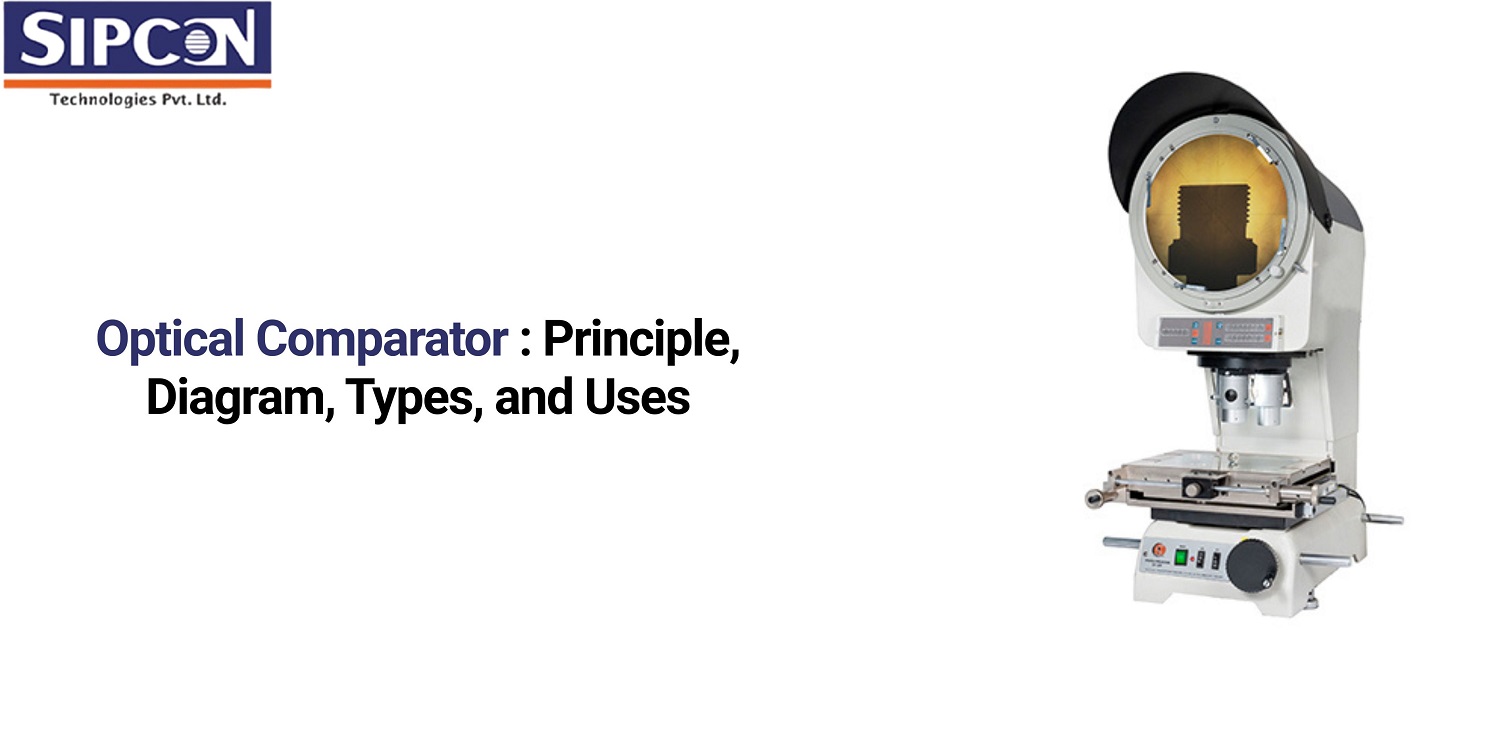
Optical Comparator: Principle, Diagram, Types, and Uses
The accuracy in dimensional measurement is vital, especially in manufacturing and quality assurance. The older methods, including micrometers and calipers, may be subject to human error and may not be suitable for intricate or minute parts. This is where optical comparators are required.
An optical comparator is an advanced device that utilizes light, magnification, and a projected image to provide non-contact, high-accuracy examination of manufactured components. It serves to detect deviations from designs, ensuring design conformity. This not only avoids defects but also saves time and minimizes wastage, thus enhancing the overall production process and providing increased customer satisfaction.
What is an Optical Comparator
An optical comparator is a high-precision measuring instrument used to inspect the dimensional accuracy and surface features of parts. It works by projecting a magnified image of the part onto a screen, allowing for accurate, non-contact measurement and comparison against design specifications.
A standard template or computer model can be compared with the projected image visually by operators, and without physical contact, parts can be confirmed to conform to design specifications.
The two main setups of optical comparators are horizontal and vertical. Here is how they operate:
- Horizontal comparators: With a horizontal model, the light from the optical comparator moves horizontally, meaning the observer is viewing a side silhouette of a part.
- Vertical comparators: The light of the optical comparator travels vertically in a vertical model, and therefore, the viewer is seeing the part from above. This is most effective for flat parts that can be placed on the work stage, such as gaskets.
What is Optical Comparator Working Principle
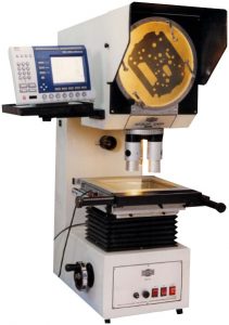
The working principle of an optical comparator is based on the projection of light. A part is placed on the stage, and light is passed through or reflected off it to create a magnified image. This image is projected onto a screen using lenses and mirrors, allowing precise measurement and comparison with standard profiles or CAD overlays without physical contact.
Optical Comparator Diagram and Components
The Optical Comparator Diagram consists of key components such as a light source, a condenser lens, a projection lens, a mirror, and a screen. These parts work together to magnify and project the profile of a part for precise visual inspection.
Explanation of Optical Comparator Diagram:
- Light Source: Offers light for the projection of the silhouette of the part. Halogen or LED lamps are used.
- Condenser Lens: Directed the diverging light from the source into a parallel beam, providing a clear image.
- Objective Lens: Condenses the light entering from the part to create the magnified image.
- Green Filter: Rejects unwanted wavelengths from the light source, typically employing green light for enhanced image quality.
- Fixed and Movable Mirrors: These are used to reflect the light beam, occasionally with the use of a plunger, to send the image to the screen.
- Screen: Shows the enlarged image of the part, usually with a grid or overlay for measurement.
- Stage: A platform that supports the part to be inspected, enabling accurate positioning and translation.
- Digital Readout: New comparators can have a digital readout for easy and precise measurement reading.
- Overlays: Translucent sheets with grids, angles, or other measurement scales, superimposed on the screen for comparison with the projected image.
Different Types of Optical Comparator
The types of profile projectors include surface optical, vertical optical, and horizontal optical comparators. Each type varies in functionality, with some offering advanced features like digital readouts, enhanced magnification, and computer integration for accurate measurement analysis.
Profile Optical Comparator
The profile optical comparator is the most universally applied and flexible. It casts the outline or profile of the object directly onto the glass screen with the help of a powerful light source positioned behind it. This creates a silhouette image that can be enlarged and compared against a scale or template. The profile comparator is particularly helpful for comparing intricate contours, radii, groove diameters, or thread forms.
Surface Optical Comparator
The surface optical comparator is designed to examine not only the outline but also the surface features of a workpiece. Rather than positioning a light behind the object, a reflection technique is employed. Light is directed at an angle and bounces off the object’s surface towards the mirror and subsequently to the glass screen.
Vertical Optical Comparator
A vertically oriented optical comparator uses a vertical optical path. The light travels upwards from the light source through the object laid flat on a glass plate. This is especially handy for observing flat or miniature components. The vertical comparator ensures stability on observation, minimizing movement or vibration, making it suitable for delicate or miniature parts.
Horizontal Optical Comparator
The horizontal optical comparator is built with its optical path in the horizontal direction. The light is thrown from the back of the object to its profile. This is more commonly used for bigger or heavier parts that are simpler to align on the horizontal plane. The design of the horizontal comparator is well-suited for positioning heavy or irregular parts directly on its stage.
What is the Use of Optical Comparator
Optical Comparator is used to inspect part dimensions and identify surface imperfections such as scratches or dents. It allows precise, non-contact evaluation, making it ideal for high-accuracy quality checks with minimal physical handling.
Inspection of Machine Parts
Perhaps the most important application of an optical comparator is quality control after or concurrent with the production process. Machined parts commonly have intricate profiles, dimensions, radii, or hole diameters that must fall within close tolerances.
Thread Inspection
Threads — both internal and external, need to be of high precision so they can be assembled correctly. The pitch, depth, angle, or profile of screw threads are most often checked with an optical comparator to ensure compliance with industrial standards. This avoids thread fit or operating issues in the finished product.
Inspecting the Profile of Cutting Tools
Drilling tools, mills, or form cutters require their cutting edges to be accurately ground. An optical comparator assists in checking their profile and size for efficient performance and accurate cutting. This ensures tool quality and the resultant quality of produced parts.
Measurement of Distances and Dimensions
Distance between slots, holes, or other features may be directly measured with high precision using an optical comparator’s grid lines, screens, or digital readouts. It is therefore a method of choice for dimensional control when conventional measuring instruments may prove challenging to employ because of intricate geometry.
Templates and Standard gauges are compared
At times, components produced must be compared to a master template or gauge to compensate for minute deviations. Optical comparators allow inspectors to overlay the projected image directly over the template’s profile or gauge, making measuring and identifying differences straightforward.
General Quality Control and Inspection
In general, optical comparators are extensively employed in process verification and quality control to manage production variances, minimize loss, prevent defects, and ensure conformity to specification. They allow firms to manufacture quality products while maintaining control of dimensions, form, and surface characteristics.
Advantages and Disadvantages of Optical Comparator
While optical comparators are a handy, precise, and contactless method to measure and inspect components, they also have their limitations. One should consider both advantages and disadvantages to decide if this tool is right for your use.
| Advantages | Disadvantages |
| Non-contact measurement — ideal for delicate or small components | Requires careful maintenance and proper lighting |
| Allows for high precision and accurate comparison | Limited by resolution; not suitable for very large or heavy components |
| Inspection is faster and more convenient | Image may be influenced by surface finish or color |
| Ability to measure complex profiles or contours | Requires trained personnel for operation |
| Large magnification helps identify small deviations | The initial cost is higher than many conventional instruments |
| Suitable for comparing dimensions against a standard profile or template | Less effective for 3D or internal dimensions |
| Helps in reducing human error during inspection | Some models may suffer from distortion or aberrations |
Conclusion
The optical comparator is a reliable tool for high-precision measurement of dimensions and profiles. Its non-contacting nature, magnification power, and straightforward comparison process make it particularly valuable for intricate or sensitive parts. Although there are some drawbacks involving cost, training, and resolution, optical comparators are invaluable in most manufacturing and quality control applications.