

Flash and Burr Measurement in Moulded Components: Cutting Rework Costs in Automotive Supply
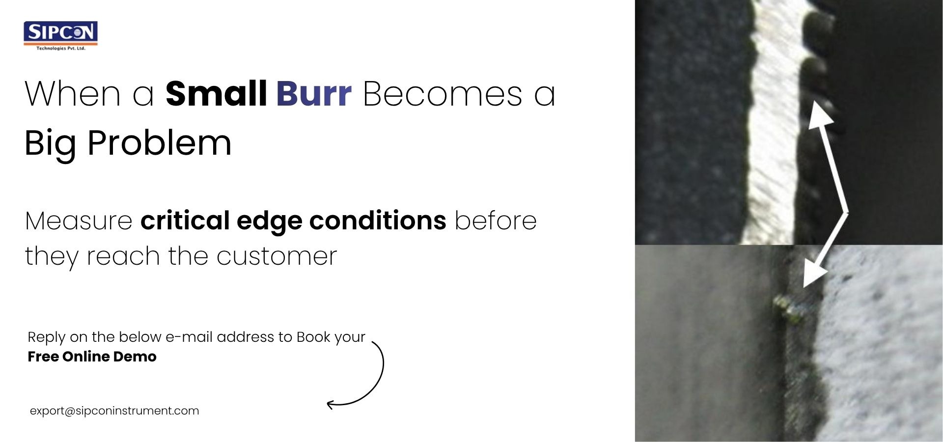
Flash and burr are small defects with a high cost. In moulded automotive components, a thin sliver of excess material at the parting line or gate can trigger deflashing labour, scrap, and customer rejections. A dedicated flash measurement machine quantifies these defects objectively. That lets suppliers in Brazil control them at source rather than pay for them downstream.
What Flash Costs You: Deflashing Labour, Scrap, Warranty, Customer PPM
Flash rarely appears on a cost report by name, yet it drains margin through several channels. Deflashing labour is the most visible. Operators trimming excess material by hand add direct cost to every affected part. Scrap follows when flash or burr pushes a dimension out of tolerance. Beyond the factory, escaped defects raise warranty claims and inflate the customer PPM (parts per million) figure used on supplier scorecards.
For an automotive supplier, a rising PPM is more than a statistic. It threatens preferred-supplier status and future contracts. Accurate measurement is the first step toward controlling all four cost channels.
Why Visual Inspection Cannot Hold a Tolerance?
Visual inspection is still common, but it cannot hold a dimensional tolerance. The human eye cannot reliably resolve a burr height of a few hundred microns. Judgement also drifts between operators and across a shift. A gauge repeatability and reproducibility (GR&R) study on manual burr assessment in Brazil usually reveals wide variation.
The result is inconsistent sorting. Good parts are scrapped, while marginal parts reach the customer. Answering how to measure flash on moulded parts with any rigour requires a quantitative, operator-independent method.
ISO 13715 and How Burr Limits Get Specified on Drawings
Burr and edge conditions are specified under ISO 13715. The standard defines edge states, permitted burr direction, and the maximum burr size a drawing allows. A designer marks the edge with a symbol and a value, for example, a permissible burr of 0.3 mm in a stated direction.
An auditor checks conformance against this callout. Whatever equipment a supplier selects, it must resolve the specified limit and produce a record traceable to the drawing. Burr measurement is therefore a defined engineering requirement, not a subjective visual check.
Automated Flash Measurement: How the System Works
An automated flash measurement system captures the part optically and measures its outline without contact. Backlight illumination casts a sharp silhouette of the profile. Telecentric optics keep magnification constant across the field, and sub-pixel edge detection locates the true boundary of the part and any flash beyond it.
Because the method is non-contact, it does not deform soft or thin flash. The system reports flash and burr dimensions against the tolerance and returns a clear pass or fail. In Brazil, burr height measurement equipment built this way takes the operator out of the measurement itself.
One-Click Measurement: A Full Part Report in Under a SecondSpeed is the decisive advantage. A one-click measurement system captures the entire field of view in a single image and measures every feature within it at once. There is no cross-hair to align and no point to probe in turn.
An instant dimension measuring machine returns a full part dimension report in under a second. The operator places the part, presses once, and reads the result. For high-volume moulding, this throughput lets a supplier inspect far more parts without adding labour. The gap between sampling and full inspection narrows sharply.
Using Measurement Data to Correct the Mould, Not Just Sort the Parts
Sorting parts treats the symptom. The greater value lies in correcting the mould. Because the system records every measurement, it builds a trend over time. A steadily growing flash dimension at one cavity signals parting-line wear—a burr appearing at a gate points to a specific tooling fault.
Fed into statistical process control (SPC), this data shows the tool room where and when to act. Maintenance becomes predictive rather than reactive. The supplier corrects the cause, so fewer defective parts are produced altogether. That upstream fix delivers a larger saving than any sorting operation.
Integrating Inspection into Production Flow, Not the QC Lab
Traditional inspection lives in a separate QC lab, removed from the moulding machine both physically and organisationally. Parts travel to the lab, wait in a queue, and get measured hours later. By then, a drifting process may have produced a full shift of suspect parts.
A fast, simple video measuring machine for plastic parts can move onto the shop floor. Placing it in the moulding cell, it gives the operator immediate feedback after each cycle or batch in Brazil. Inspection becomes part of the production flow, not a downstream gate. Problems surface in minutes instead of hours.
ROI Model: How Fast Does the Machine Pay Back at Your Rework Rate?
The payback case is direct and depends on the current rework rate. Three levers drive it:
- Deflashing labour hours removed per shift.
- Scrap reduction as tolerances hold.
- Warranty and PPM penalties avoided.
A simple model frames the effect:
| Factor | Before automated measurement | After |
| Deflashing labour | High, manual trimming | Reduced, applied only where needed |
| Scrap rate | Higher, inconsistent sorting | Lower, quantified limits |
| Customer PPM | Elevated | Controlled |
| Inspection speed | Minutes per part | Under one second |
At a typical automotive rework rate, the combined labour and scrap saving often returns the machine cost within months. The exact payback depends on volume and current defect levels, which a sample-part demonstration can quantify precisely.
Explore the flash measurement system, the instant dimension measuring machine, and the video measuring machine for plastic parts in Brazil, or browse the full product range.
Request a sample part demonstration → or get pricing from our team.
Frequently Asked Questions
1. Q: How do you measure flash on moulded parts accurately?
Ans: A flash measurement machine captures the part as a backlit silhouette and applies telecentric optics with sub-pixel edge detection to locate the outline. Flash and burr dimensions are measured against the drawing tolerance without contact, giving a repeatable, operator-independent pass or fail.
2. Q: What does ISO 13715 require for burr measurement?
Ans: ISO 13715 defines edge states and the maximum permitted burr size and direction on a drawing. A designer specifies a burr limit, for example, 0.3 mm, and inspection must resolve and record it. Compliant burr measurement ties each result back to the drawing callout.
3. Q: How quickly does a flash measurement system pay for itself?
Ans: Payback depends on the rework rate. Savings come from reduced deflashing labour, lower scrap, and avoided PPM penalties. At typical automotive volumes, the combined saving often covers the machine cost within months. A sample-part demonstration gives an exact figure for a specific part.