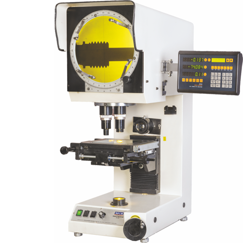
Vertical
Profile Projector
Next-generation profile measurement with speed and accuracy.
- High precision for gears, tools, and rubber parts
- Supports multiple measurement applications
- Non-contact measurement ensures zero part damage
From Focus to Illumination
Built for Perfect Profile Inspection
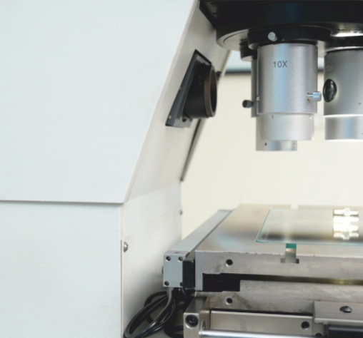
Focusing By Moving Projection Screen
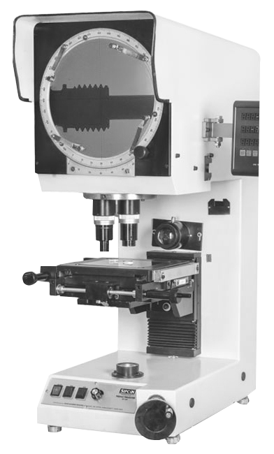
The Vertical Profile Projector is a high-precision profile measuring machine designed for accurate dimensional inspection of small, intricate, and critical components. With its unique focusing by moving projection screen mechanism, it ensures sharp, distortion-free images, making part inspection simple, fast, and highly reliable.
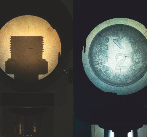
Outstanding Illumination
With precision optical projectors, consistent illumination plays a vital role in achieving repeatable and error-free results. Whether inspecting rubber parts, cables, or complex profiles, the projector guarantees crystal-clear visibility for precise dimensional measurement.
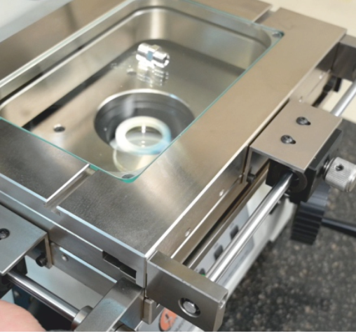
Threadless Workstage
designed for effortless movement and long-term precision. Unlike conventional threaded stages that may wear out or cause jerks during operation, the threadless design ensures frictionfree and smooth travel of the measuring table. This enhances accuracy while inspecting components and makes handling easier for operators.
Technical Data for Camera Based Profile Projector
-
SCREEN
Size: 300/400 mm Construction: Opaque glass screen with 90° cross line fitted with graduated rotary line (0-360°) operated by knob, L.C. 1 min. -
WORKSTAGE SIZE
Std: 250 mm x 250 mm Opt: X-axis upto 550 mm, Y axis upto 350 mm -
MEASURING RANGE
Std: 100 mm x 100 mm Opt: Upto X axis - 400 mm, Y axis - 200 mm -
LIGHT AXIS
Vertical -
FOCUSING
90 mm/100 mm
-
LINEAR MEASUREMENT
Micrometers/Built in glass scale -
OPTICS
Std: 10X Opt: 20X, 50X, 100X Mount: 3 lens turret mount/Screw mount -
ACCURACY
Magnification: #0.05% (Contour/Surface) Measure: 3 + L/100 um -
MEASURING SYSTEM
Micrometer/D.R.O./PC based software -
COOLING SYSTEM
Fan -
ILLUMINATION
Contour: 24V/150W halogen lamp, illumination control with condenser unit provide light as per lens Surface: Twin 24V 150W halogen lamp
-
RESOLUTION
Linear: 0.001/0.0005 mm Angular: 1 sec -
MOTORIZED MOVEMENT
Opt: (x, Y, focusing with speed control) -
OPTIONAL HARDWARE
Profile Charts, Rotary Table, V-block, Centre Holding Device Opto Edge Sensor, Rotary Encoder -
POWER SUPPLY
AC - 110/220V (50/60 Hz) single phase -
STAND
Unique rigid pedestal system facilitates vibration free handling of component
Precision at Your Fingertips with DRO Systems
A Simple & Innovative
Readout Solution
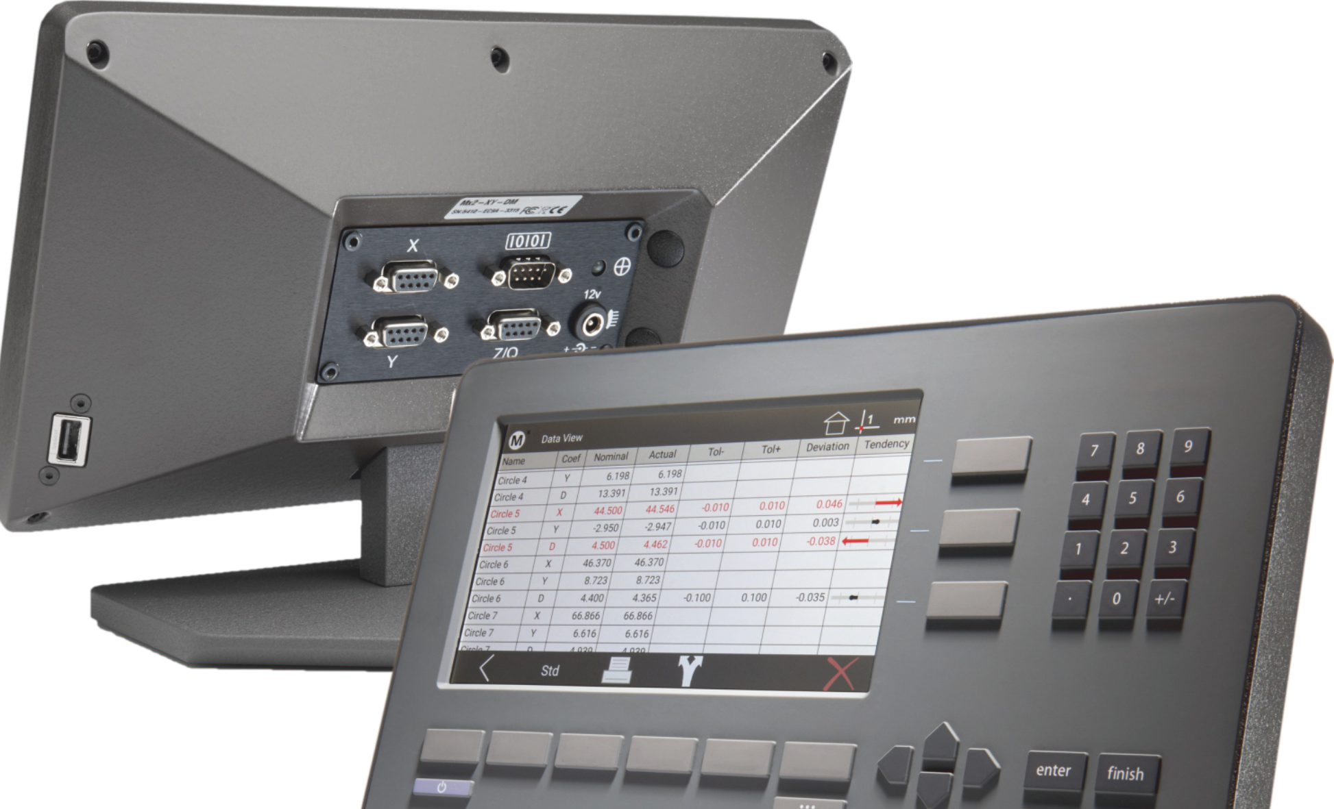
- METLOGIX'S MLX-200
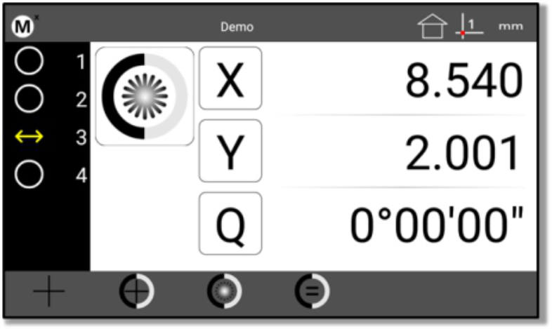
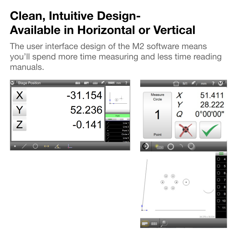
Clean, Intuitive Design
Combining a familiar user experience with current touchscreen conventions, the Mx200 readout can quickly be integrated into your process while being accessible to a wide range of users.
Report Print Export
Choose from one of three report formats; CSV, Standard, or Tolerance. Report contents can include a report title, time and date stamps, and all feature measurement result data.
Export choices include:
Paper Printer(USB, Wifi,Bluetooth), Save to file (USB), RS232 Output
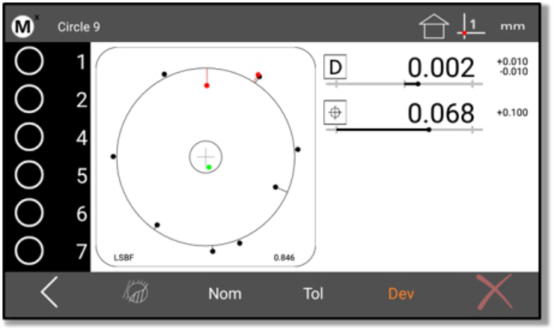
Geometric Tolerancing & Part Programming
Apply popular geometric tolerance controls to measured and constructed features using the industry leading Metlogix tolerance system. Apply nominal and tolerance limits quickly, and view results accurately, in the large and easy to read data views. Record inspection routines for simple playback of measurements, tolerance controls, and data handling and printing steps.

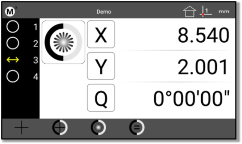
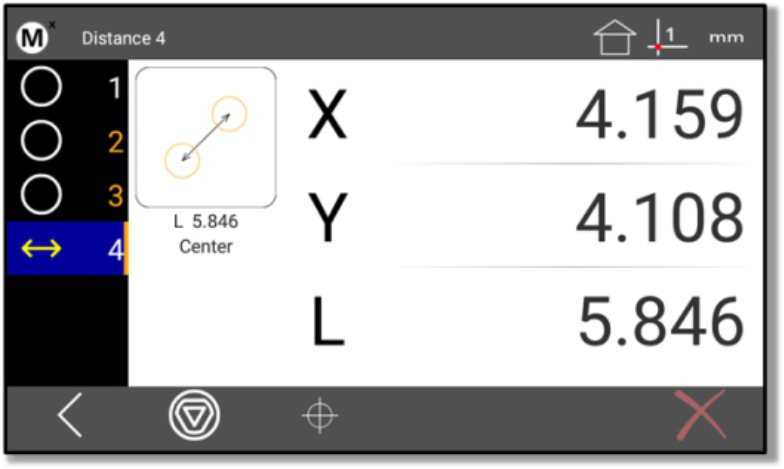
Optical Edge and Crosshair Probes
Available for both Optical Edge and Crosshair only measurement systems the Mx200 probing options are simple and intuitive. The exclusive EdgeLogic™ feature enables gesture driven control of start and end measurement commands, alleviating the need to interact with the DRO directly. Just cross the same edge twice to start and end measurements!
Wireless Data Transfer
Transfer measurement data instantly and wirelessly from your Мx200 readout to a network window computer.
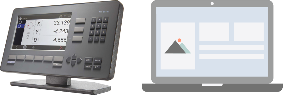
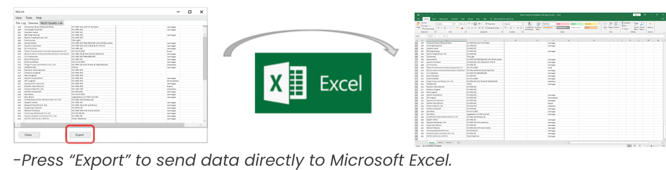
Transfer MxLink data directly to Excel
For more advanced data calculations simply press Export to transfer selected MxLink results to a blank Excel sheet.
Measuring Software
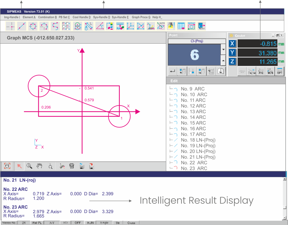
SIPMEAS
M2 Measuring Software
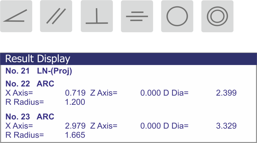
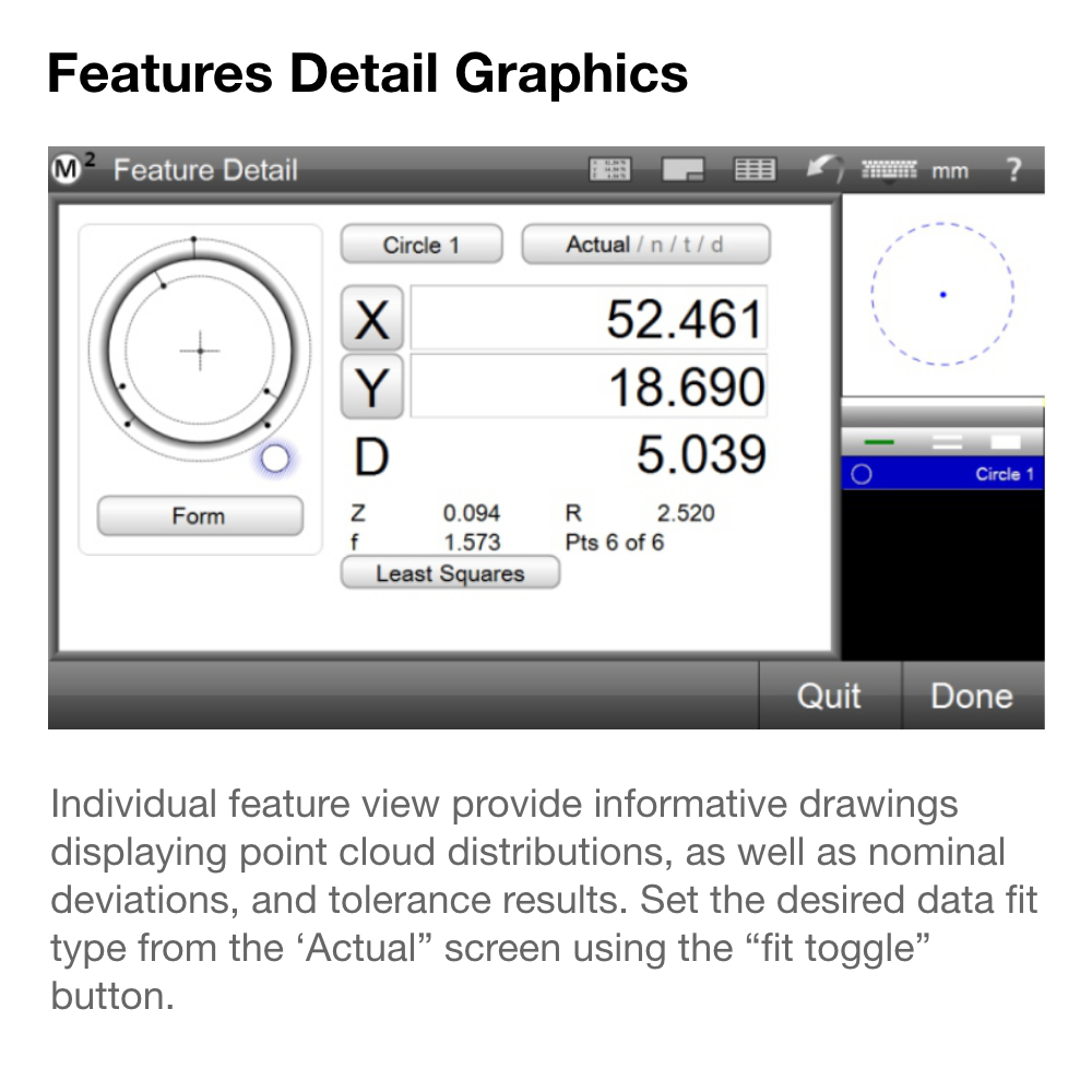
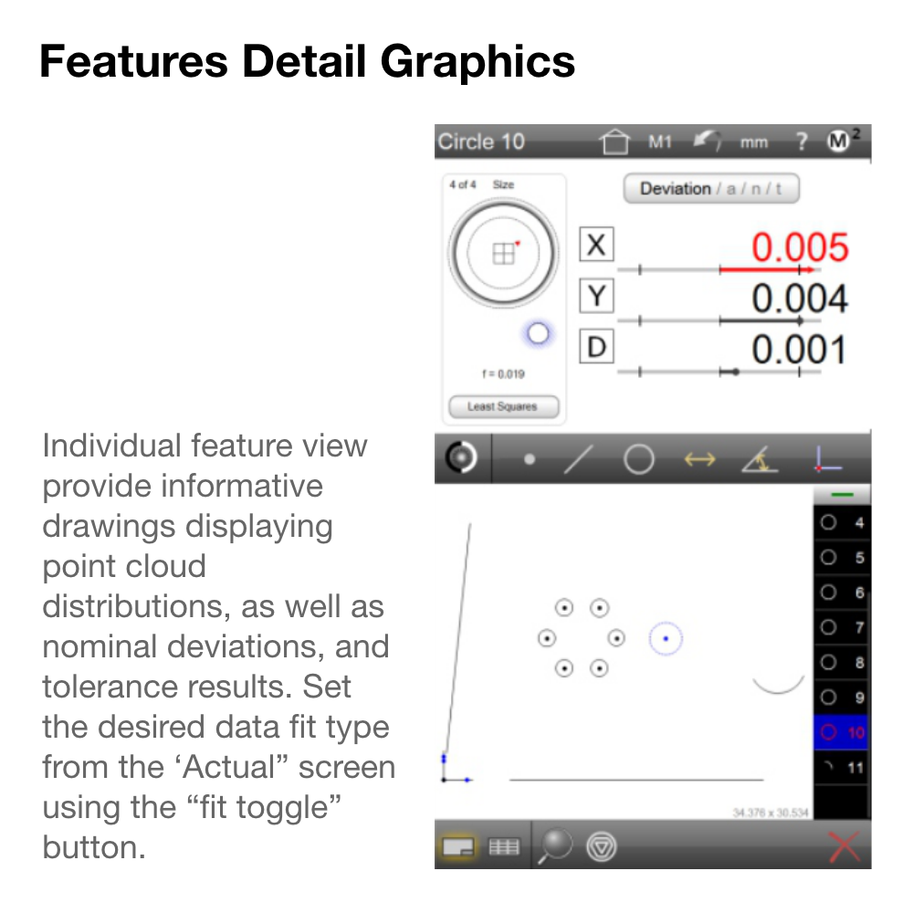
Tolerance Setting & Result Display
Software Desktop
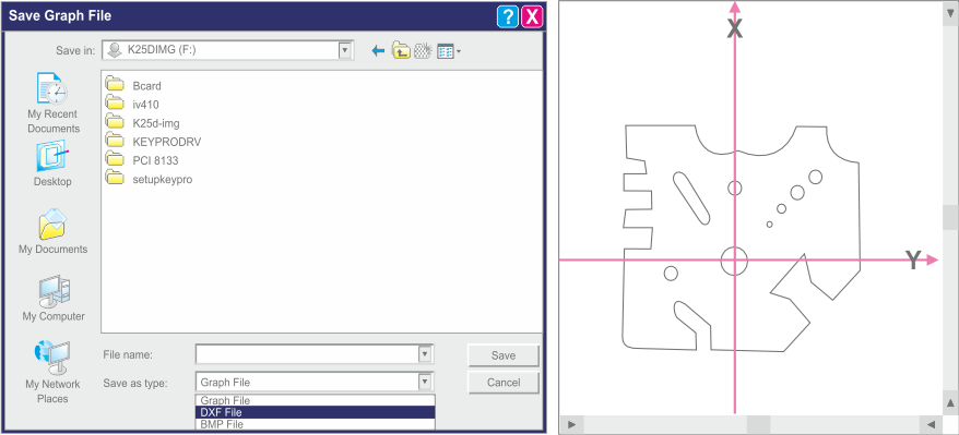
Data Management-Export and Calculations
Directly saving graphs as DXF or IGS files makes it possible to export our measurement to CAD.
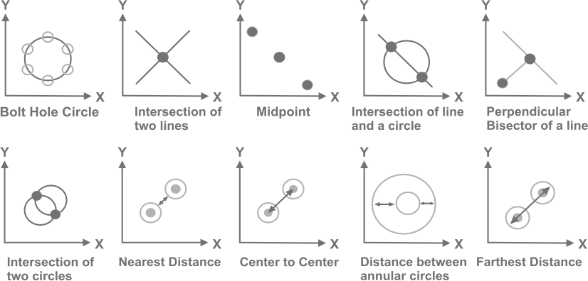
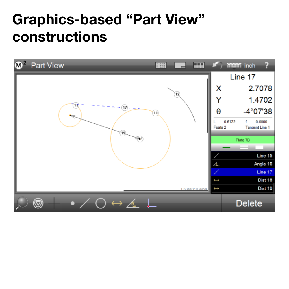
Construction Capabilities
Select two or more features to create intersections or constructions.
M2 Measuring Software
-
Features
2D- Point, Lines, Circles, Arcs Slots, Rectangles, Blobs Distances, Angles -
Calibrations
LEC, SLEC, NIEC -
Applications
Reverse engineering In line production Quality inspection -
Constructions
2D- Point, Lines, Circles, Arcs Midpoints, Mid Lines, PCD, Distances, Intersection, Bisectors, Offset, Angles -
Tolerances
Size, Form, Orientation, Position, Runout -
Programming
Measure & program -
Measurement Modes
Polar/Cartesian, DMS/ DD, MM/ INCH -
Datumming Features
Skew Alignment Datum (Origin) Points Reference Axis Rotation & Skew -
Exports
PDF, DXF, Excel, CSV, TSV(Tab) Data trasmit to RS 232 port


Contact Us
Let’s Tackle Your Toughest Measurement Problems—Start Here