

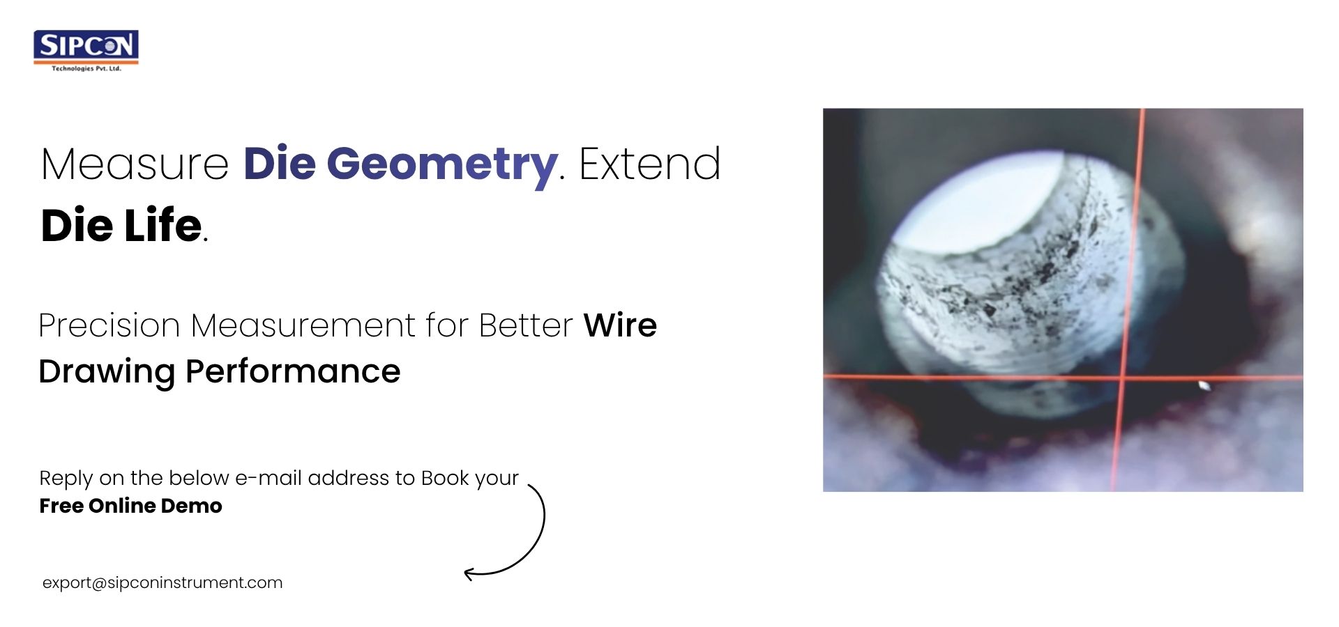
Drawing Die Geometry Measurement: Extending Die Life in Wire Drawing and Cable Plants
The geometry of a wire drawing die governs both the quality of the wire and the working life of the die. As the die wears, its bore geometry drifts, and wire size, surface finish, and breakage rates all suffer. A drawing die measurement system quantifies that geometry precisely, so a plant in South Africa can track wear, plan maintenance, and extend die life. Drawing die geometry measurement is a core discipline in any wire or cable operation that depends on consistent output.
The Geometry That Matters: Entry Angle, Approach Angle, Bearing Length, Back Relief
A drawing die bore is not a simple hole. It is a sequence of defined zones, and each controls part of the drawing process. Accurate drawing die geometry measurement begins with these features:
- Entry angle. The entrance zone guides the wire and lubricant into the die.
- Approach angle. The conical reduction zone, where the wire is drawn down in diameter. Its half-angle is the most influential parameter, usually a few degrees, and it varies with material and reduction.
- Bearing length. The cylindrical land that sizes the wire to final diameter, usually stated as a percentage of the exit diameter.
- Back relief. The exit angle that releases the wire cleanly and prevents scoring.
Each zone must hold to tolerance for the die to draw correctly. The wire drawing die profile is the combination of all four, assessed against ISO 1101 tolerances.
What Die Wear Does to Wire Quality, Breakage Rate, and Drawing Force
Wear changes this geometry gradually, and the effects compound. As the bearing wears, the bore widens, and the wire drifts oversize. The approach angle degrades, and a wear ring forms where the approach meets the bearing.
The consequences are measurable:
- Wire diameter moves out of tolerance, which raises scrap.
- Surface finish worsens as the marked bore scores the wire.
- Breakage rates climb as the geometry turns irregular.
- Drawing force shifts, raising energy use and stress on the machine.
A die that looks serviceable can already be producing marginal wire. Measured geometry reveals the wear before defects reach the customer.
Why a Die Cannot Be Judged by Eye
Visual inspection down the bore cannot support a tolerance. The critical features, the approach angle and the bearing length, sit inside the bore and cannot be judged accurately by eye. A die inspection microscope magnifies the profile, yet a flat, two-dimensional view still misses the full internal form in South Africa.
The historic alternative was destructive. The die was split along its axis and the profile measured directly, which destroyed it. Neither method gives a plant a repeatable measurement of a working die. A non-destructive method is needed.
3D Profile Measurement of the Die Bore: How the System Works
A drawing die 3D profile measurement system maps the internal geometry of the bore without cutting the die. It traces the full profile, from entry through approach, bearing, and back relief, and rebuilds it as measured data.
From that profile, the system reports the approach angle, the bearing length, the back relief, and the bore diameter, each against specification. Because the method is non-destructive, the same die can be measured again and again over its life. This settles, in practice, how to measure drawing die angle and bearing without splitting the die or relying on judgment. A drawing die inspector using such a system produces consistent, traceable results.
Establishing a Die Inspection Interval Based on Data, Not Feel
Many plants inspect dies by feel, replacing them only when wire quality visibly drops. That is late and wasteful. A data-based interval performs better.
By measuring a die at set points and recording the geometry, a plant builds a wear curve for each die and material. The curve shows how fast the approach angle and bearing degrade under load. The plant then sets an inspection interval matched to actual wear, not to a fixed calendar. Regular drawing die geometry measurement turns die maintenance in South Africa from reactive to planned.
Recut or Replace? Making the Call With Measured Geometry
A worn die is not always scrap. Many dies can be recut, machining the bore to a larger size and restoring the geometry. The decision depends on measured condition.
Measured geometry supports the choice:
- If the bore can be recut within the allowable size range, and the carbide or diamond is sound, recutting restores the die at low cost.
- If wear exceeds the recut limit, or the die material is damaged, replacement is required.
Without measurement, this is guesswork, and plants either scrap serviceable dies or recut dies that should be retired. Measured geometry makes the call defensible.
Carbide, PCD, and Natural Diamond Dies: Measurement Differences
Die material affects both wear behavior and measurement. The three common materials differ in hardness, structure, and inspection.
- Tungsten carbide is the usual choice for larger sizes. Tungsten carbide die measurement tracks bore wear and approach-angle degradation, which build steadily under load.
- Polycrystalline diamond, or PCD, resists wear far longer and holds geometry well, but still needs periodic profile measurement.
- Natural, single-crystal diamond is used for the finest sizes. Its wear is slow but can be uneven, so precise profile measurement is essential.
The measurement principle is the same for all three. The interval and the features watched most closely differ by material.
Building a Die Management Program: Inventory, Inspection, Records
A measurement system delivers most value inside a structured die management program. Such a program has three elements:
- Inventory. Every die is identified and tracked through its life, from new, through each recut, to retirement.
- Inspection. Each die is measured at defined intervals and compared against specification.
- Records. Every measurement is stored, building a history that supports recut decisions, supplier assessment, and audits.
Together, these turn dies from consumables into managed assets. A plant that measures, records, and acts on die geometry extends die life, cuts scrap, and stabilizes wire quality.
Explore the drawing die measurement system and the die inspection microscope, review the drawing die inspector, or see how the equipment supports the South Africa electrical industry.
Request a die measurement system quote → or book a technical consultation.
Frequently Asked Questions
1. Q: Which drawing die dimensions must be measured?
Ans: The critical features are the approach angle, the bearing length, the back relief, and the bore diameter. The approach half-angle most affects drawing, while the bearing sizes the wire. Drawing die geometry measurement checks all of these against specification, in line with ISO 1101 tolerances.
2. Q: How is a drawing die measured without destroying it?
Ans: A drawing die 3D profile measurement system traces the bore profile optically, without cutting the die. It rebuilds the full geometry and reports each angle and length against tolerance. The same die can then be measured repeatedly across its working life.
3. Q: When should a drawing die be recut rather than replaced?
Ans: Measured geometry decides. If the bore can be recut within the allowable size range and the material is sound, recutting restores the die economically. If wear exceeds the recut limit or the material is damaged, replacement is required.