
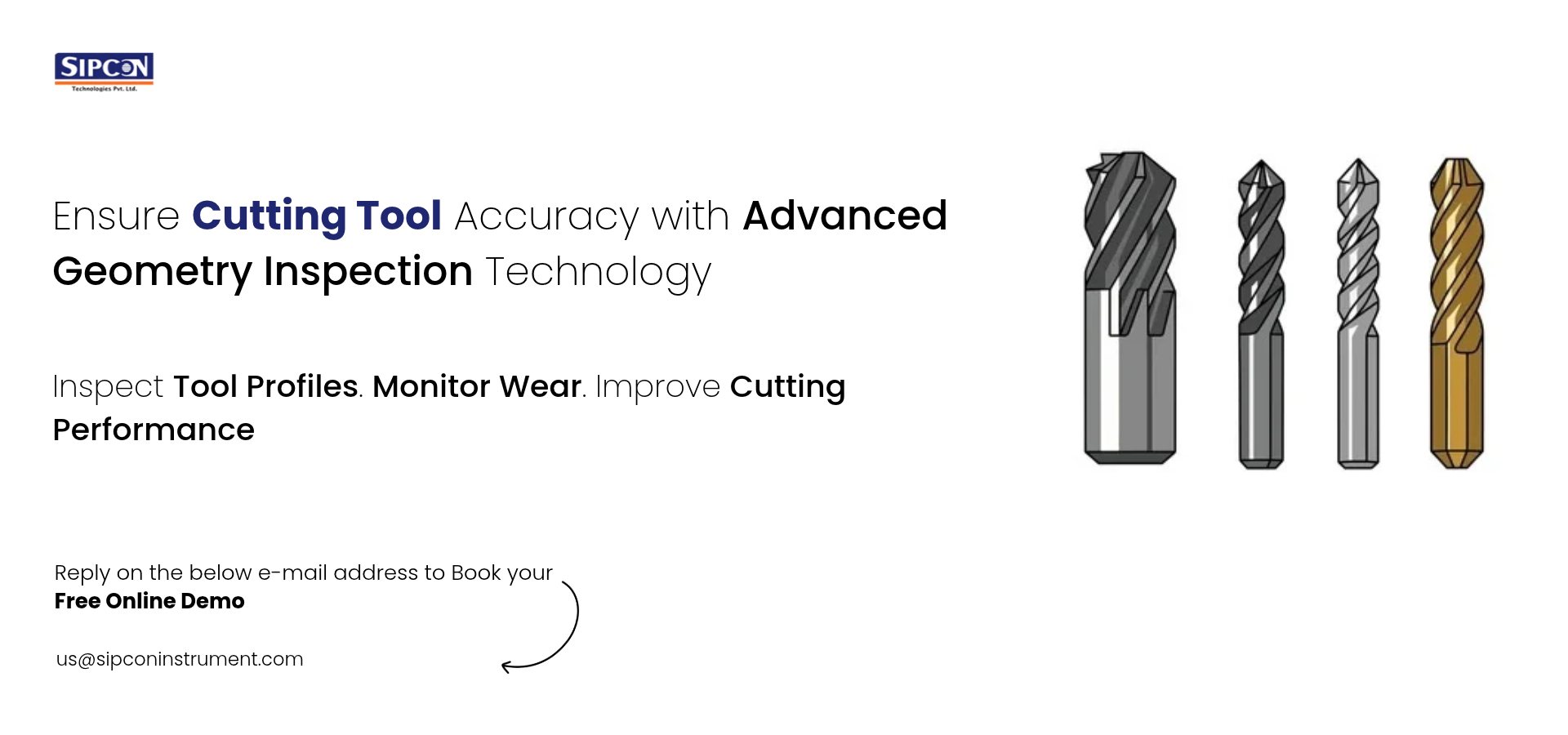
Cutting Tool Geometry Inspection in USA: Measuring Flute Profile, Cutting Edge, and Tool Wear
A tool can have the correct diameter, but cut poorly for many reasons. Perhaps it is chipped, or has worn flutes that change how chips flow through the cut. Even so, some cutting tool problems can escape detection by the naked eye.
Tool checks by cutting tool systems enable US machine shops to identify these cutting tool problems before using the tool on the job. Machine shops can review the cutter shape and condition. The Cutting tool inspection system USA should consider cutting tool checks required for their parts.
Why Cutting Tool Geometry Inspection Matters in Precision Machining
Cutter inspection allows shops to know the job’s cutting requirements and know whether to use a regrind or replacement tool. It also allows shops to see how cutting tool geometry has changed through use, grinding, or improper tool manufacturing.
Cutting tool geometry measurement also has applications in troubleshooting manufacturing parts failures. Has the geometry of the tool exceeded allowable limits? Then, examine the work holding, spindles, coolant delivery systems, and machine settings.
Key Parameters: Flute Profile, Diameter, Length, Rake Angle and Cutting Edge
For best results, check tool drawings. Make sure measurements have clear labels, so it is obvious which part of the tool is referenced.
Flute Profile
The flute is the channel of an end mill or drill. Flute shape allows room for chips of material to leave the tool’s cut. Flute shape should be measured and compared against design, where the sensor can see it.
Diameter and length
Cutting diameter is the dimension from one side of the cutting edges to the other. To find this measurement, take measurements at specific locations on the tool. Because a tapered tool does not have a consistent diameter throughout its length, you cannot expect to find the exact same measurement at every point.
The length could be the total length of the tool, the length that cuts, or the distance the tool extends beyond its holder. Indicate what type of length is shown in this report.
Rake angle and edge shape
The rake face is where the chip flows. This angle determines what type of cut will be made with the tool. Measure this angle relative to the plane of the tool drawing or testing method.
Cutting edge radius measurement determines the size of the rounded area that forms at the intersection of the rake face and the flank. The cutting edge radius is different than the corner radius of an end mill. Some edges may be honed unevenly on purpose. Sometimes a single radius measurement cannot fully describe the surface topography.
Optical Inspection of Drills, End Mills and Reamers
Optical techniques detect objects without contact by utilizing light and video technology. Backlighting reveals the contour of the tool while front-lighting highlights surface characteristics. In areas where the 2D view is insufficient, a well-chosen 3D sensor adds the necessary depth information.
Depending on the type, a tool might be checked in different ways;
- The drill geometry inspection can check the point angle, cutting lips, diameter, and edge chips.
- End mill inspection can be used to check the cutting flute spacing, cutting depth, corner shape, and edge wear.
- Reamer inspection may verify the size, tip lead, and wear of the cutting edges.
The view matters as much as the camera. A deep groove may hide part of a surface. The tool may need to turn or tilt so the sensor can reach it. Which features can the setup measure? Ask for proof. A sharp image alone is not enough.
Identifying Cutting Edge Wear and Geometry Changes
A tool wear measurement system records the extent to which a tool has been worn with continued use. The measurement might include the determination of areas on the flank that have become worn, the existence of edge chips, the presence of notches, or the general change in the shape of the tool. A scan of the new tool gives the shop a baseline for future tool checks.
For a valid result, you must use a method every single time:
- Clean the tool with a method that suits its coating.
- Analyze the same edge at the same place.
- Light source, fixture, and method of test must be the same.
- Record the type of material cut as well as feeds and speeds.
Bits of the cut part can stick to the edge, causing it to seem worn instead of its real shape, or damaged through misuse of the tool. Set limits of wear as the basis of a job specification. One set of criteria will not be suitable at all times for tools, parts, or surfaces.
Tool Inspection Systems vs Tool Presetters: Different Measurement Purposes
Presetters: these instruments mainly verify the tool length and the diameter of the tool to set up machines. They can assist the workshop in setting tool offsets even prior to the cutting phase.
Instrumentation for tool inspection: such equipment not only checks tool shape but also its condition in a more detailed manner.
Overlapping between these two devices, at times, is inevitable. Some presetters now come with a camera and software capable of detecting tool edge issues too. What is written as the name of a machine does not necessarily reveal what it can actually do. Identify your sensor(s) and software that match your requirements.
Choosing a Cutting Tool Inspection Setup for USA Manufacturers
Your confidence in the assessment of the cutting tool inspection manufacturers in USA must start with trying it out. Try it out with the tools you normally use. Take a small drill bit, a coated cutter, and a really worn tool from your workshop.
Check the supplier to remove and then insert back a tool and check again. How much do the measurement results deviate from each other? Did the manufacturer also provide information on measurement uncertainty and the limit values of the technical drawing? High accuracy of a digital display alone does not indicate the accuracy of the measurement result. 
Also take a close look at training, type and style format of reporting, calibration, and US-based technical service support availability. The solution must be compatible with the tools you have. And the user interface should not be too complex a task for your team!
Dare to have a deeper look into the condition of your tools? Set up a test session and request a transparent breakdown of features relevant for your workshop.
Contact Sipcon Instrument USA at +1 (262) 391-4785 or us@sipconinstrument.com today.